按关键字搜索知识库
Strain Gauges vs. Piezoelectric Sensors
应变片与压电传感器
Many industries require weighing or measuring forces to perform their principal tasks. Strain gauges and piezoelectric sensors are two common transducer technologies that serve these industries.
许多行业需要称重或测量力来执行其主要任务。应变片和压电传感器是服务于这些行业的两种常见传感器技术。
Both transducers are widely used for almost the same applications. However, differences exist between these sensors. For one, performance factors differ such as resolution, accuracy, and susceptibility to environmental errors. Secondly, utilization factors such as ease of measurement, signal transmission, equipment interfaces, and physical characteristics distinguish them.
两种传感器都广泛用于几乎相同的应用。但是,这些传感器之间存在差异。首先,性能因素不同,例如分辨率、准确性和对环境误差的敏感性。其次,易于测量、信号传输、设备接口和物理特性等利用因素使它们与众不同。
This article compares and contrasts these two types of sensors. It provides information to help system designers select components for a given application. Moreover, it aims to provide general information on how instrumentation and control systems use these devices.
本文对这两种类型的传感器进行了比较和对比。它提供的信息可帮助系统设计人员为给定应用选择组件。此外,它还旨在提供有关仪表和控制系统如何使用这些设备的一般信息。
Principle of Operation 工作原理
In this section we compare the science that enables each type of sensor to convert forces to electrical signals.
在本节中,我们比较了使每种类型的传感器能够将力转换为电信号的科学。
Strain Gauges 应变片
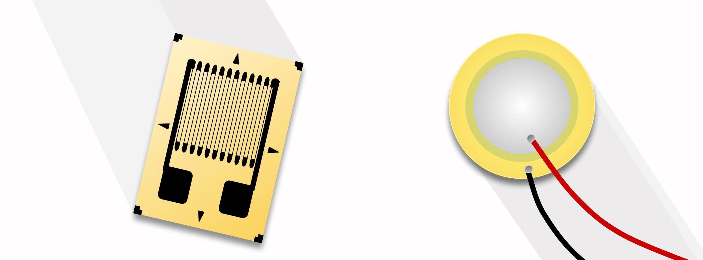
A strain gauge sensor transforms an applied force to an electrical signal through elastic deformation of the strain gauge. (See The Versatile Strain Gauge Load Cell for more information.) These forces can be static or dynamic in nature. Examples include weight, acceleration, and pressure. Internal to the gauge, this deformation in turn changes the dimensions of the strain gauge material. When the force is parallel to the gauge’s thin wiring and tensile, the wire lengthens and narrows (much like pulling a rubber band). This increases the resistance in the gauge. Likewise, a parallel compressive force widens and shortens the wire, decreasing resistance. The change in the material’s electrical resistance with either direction of force is proportional to the magnitude of the applied force.
应变片传感器通过应变片的弹性变形将施加的力转换为电信号。(有关更多信息,请参阅多功能应变片称重传感器。这些力本质上可以是静态的,也可以是动态的。示例包括重量、加速度和压力。在应变片内部,这种变形反过来又会改变应变片材料的尺寸。当力平行于量规的细线和拉伸时,电线会变长和变窄(就像拉橡皮筋一样)。这增加了仪表中的电阻。同样,平行压缩力会加宽和缩短导线,从而降低阻力。材料电阻随任一方向的力的变化与施加力的大小成正比。
The mathematical formula that relates the changes in dimension to change in resistance is:
将尺寸变化与电阻变化联系起来的数学公式为:
The output signal of the load cell is the voltage drop across this small change in resistance. This is possible due to the internal circuitry behind this delta, the Wheatstone bridge. See The Versatile Strain Gauge Load Cell for a more detailed explanation of the internal circuitry of this device. We give a simplified explanation here using one such bridge configuration: the Quarter Bridge.
称重传感器的输出信号是电阻这一微小变化两端的压降。这是可能的,因为这个三角形后面的内部电路,惠斯通桥。有关该器件内部电路的更详细说明,请参阅多功能应变片称重传感器。我们在这里使用一种这样的桥接配置给出一个简化的解释:四分之一桥。
Quarter-Bridge Configuration
四分之一桥配置
The expression below Figure 1 shows the mathematical formula for a quarter-bridge configuration. Here dR is the change in resistance of the strain gauge:
图 1 下面的表达式显示了四分之一桥配置的数学公式。这里 dR 是应变片的电阻变化:
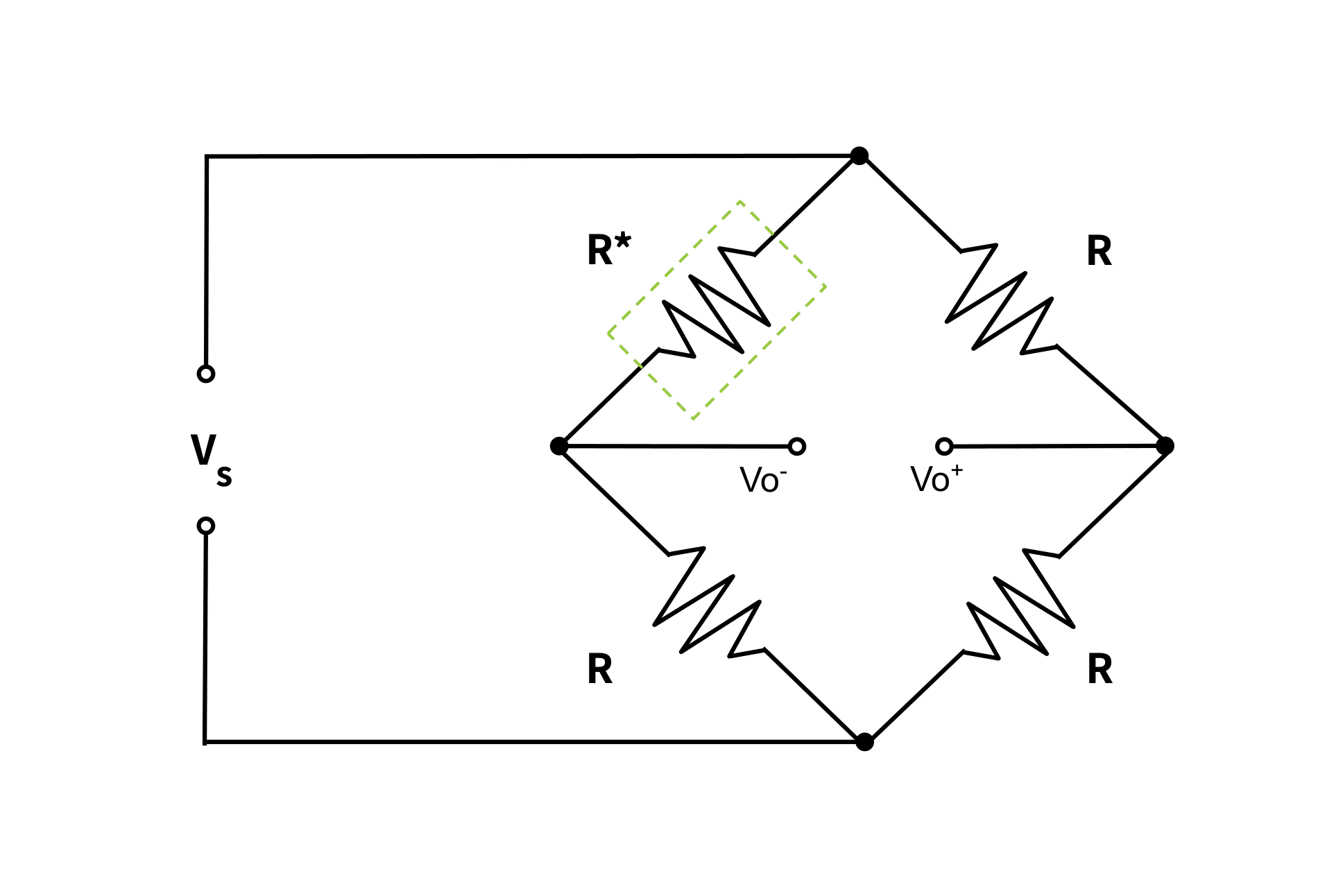
图 1.四分之一桥应变片配置
This analog output voltage is very small (mV). This makes it vulnerable to signal noise and interference. Also, the signal’s low magnitude is generally not great enough for a display to interpret. Therefore, the signal must undergo filtering and amplification through a signal conditioning circuit. For more detail on this topic, see Why Do I Need An Amplifier (and Other Signal Conditioners)?
该模拟输出电压非常小 (mV)。这使得它容易受到信号噪声和干扰的影响。此外,信号的低幅度通常不足以让显示器进行解释。因此,信号必须通过信号调理电路进行滤波和放大。有关此主题的更多详细信息,请参阅为什么需要放大器(和其他信号调节器)?
Other Configurations 其他配置
Half-bridge and full-bridge Wheatstone Bridge configurations also exist. They use two and four gauges respectively in the arms of the bridge circuit. Their multiple gauges compensate for, or eliminate strain effects other than the intended load strain. That is, the placement of additional gauges can cancel effects due to temperature, unwanted bending moments, and non-axial forces.
还存在半桥和全桥惠斯通桥配置。它们分别在桥接电路的臂中使用两个和四个仪表。它们的多个仪表可补偿或消除预期负载应变以外的应变效应。也就是说,放置额外的仪表可以抵消由于温度、不必要的弯矩和非轴向力而产生的影响。
These configurations are covered in more detail in the articles, The Versatile Strain Gauge Load Cell and All About Electrical Connections Of Force Transducers.
这些配置在文章中有更详细的介绍, 多功能应变片称重传感器 和 关于力传感器的电气连接.
Piezoelectric Sensor 压电传感器
A piezoelectric sensor makes use of a piezoelectric material. The available types of piezoelectric materials vary, but all transforms pressure into an electric charge. The magnitude of the applied load is proportional to, and therefore determined by, the quantity of this electric charge.
压电传感器使用压电材料。可用的压电材料类型各不相同,但都将压力转化为电荷。施加负载的大小与该电荷的量成正比,因此由该电荷的量决定。
Also, a piezoelectric sensor can act as a piezoelectric actuator in a process called the reverse piezoelectric effect. This effect occurs when a supply of alternating voltage to the sensor makes the piezoelectric material start to vibrate.
此外,压电传感器可以在称为反向压电效应的过程中充当压电致动器。当向传感器提供交流电压使压电材料开始振动时,就会发生这种效应。
Internal to the Sensor: Polarity of Piezoelectric Material
传感器内部:压电材料的极性
To illustrate the piezoelectric process, Figure 2 shows a manufactured crystal with polarity in steady state (leftmost drawing). The sensor’s piezoelectric material has dipoles (indicated by
为了说明压电过程,图2显示了极性处于稳态的人造晶体(最左边的图)。传感器的压电材料具有偶极子(用
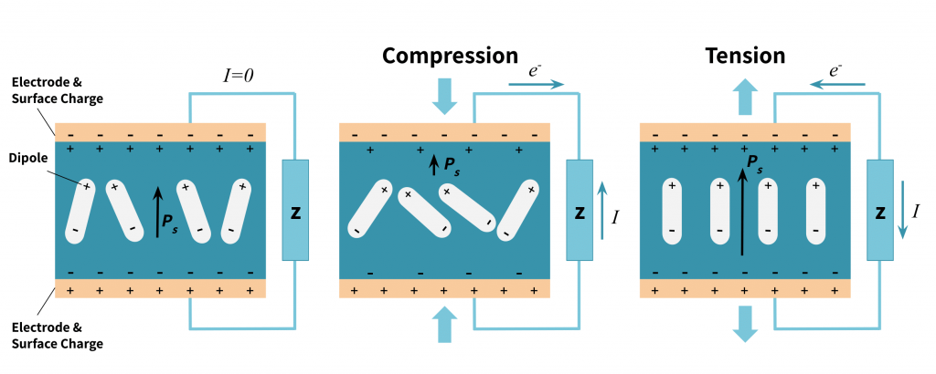
图2.压电发电
The mathematical formula for the amount of charge produced is:
产生的电荷量的数学公式为:
where
其中
Internal to the Sensor: Charge Amplifier
传感器内部:电荷放大器
A charge amplifier then detects the electrical charge between the electrodes as either a charge source or a voltage source, depending on the amplifier design. Operational amplifiers (Op Amps) are preferable since they overcome the effects of stray cable, sensor, and amplifier capacitances.
然后,电荷放大器将电极之间的电荷检测为电荷源或电压源,具体取决于放大器设计。运算放大器(Op Amps)是优选的,因为它们克服了杂散电缆、传感器和放大器电容的影响。
There are several advantages to charge amplifiers. With modern microelectronic techniques, the charge amplifier can be embedded inside the transducer to shorten the gap between the electrode and the amplifier. Furthermore, charge amplifiers compensate for charge leakages common in piezoelectric material due to its large internal resistance. The ANYLOAD A2P-D2 Load Cell Amplifier, sold by Tacuna Systems is an example of a charge amplifier.
充电放大器有几个优点。借助现代微电子技术,电荷放大器可以嵌入传感器内部,以缩短电极和放大器之间的间隙。此外,电荷放大器由于其较大的内阻,可以补偿压电材料中常见的电荷泄漏。Tacuna Systems 销售的 ANYLOAD A2P-D2 称重传感器放大器就是电荷放大器的一个例子。
Material of Construction
结构材料
This section explains the materials that make up each type of sensor. As explained above, sensor designs exploit the physical properties of these materials to convert forces to signals.
本节介绍构成每种传感器的材料。如上所述,传感器设计利用这些材料的物理特性将力转换为信号。
Strain Gauges 应变片
Strain gauge sensors use the strain gauge element as the underlying mechanism. The types of construction for these include thin-film, foil, and semiconductor strain gauges. A conductive material is bonded to a thin backing. This conductive material is usually copper-nickel, nickel chromium, platinum-tungsten alloys, and silicon for semiconductor gauges. The backing is non-conductive, and usually some form of polymer.
应变片传感器使用应变片元件作为底层机制。这些结构类型包括薄膜、箔片和半导体应变片。导电材料粘合在薄背衬上。这种导电材料通常是铜镍、镍铬、铂钨合金和用于半导体仪表的硅。背衬是非导电的,通常是某种形式的聚合物。
Piezoelectric sensors 压电传感器
Piezoelectric materials can be naturally occurring crystals like Rochelle salt and quartz. They can also be synthetic. Synthetic materials generally fall into two types: (1) crystalline such as Lithium Sulphate and Ammonium Di-Hydrogen phosphate, and (2) polarized ferroelectric ceramics such as Barium Titanate. The material chosen depends on the specific properties the application requires.
压电材料可以是天然存在的晶体,如罗谢尔盐和石英。它们也可以是合成的。合成材料一般分为两种:(1)结晶,如硫酸锂和磷酸氢二氢铵,(2)极化铁电陶瓷,如钛酸钡。选择的材料取决于应用所需的特定性能。
Method of Fabrication 制造方法
This section compares the methods of construction of the two sensor types.
本节比较了两种传感器类型的构造方法。
Strain Gauges 应变片
Bonded strain gauge fabrication involves attaching a length of a conductive strip to a thin backing. This is usually done through a process called micromachining. Micromachining usually follows the following steps:
粘合应变片制造涉及将一段导电条连接到薄背衬上。这通常是通过称为微加工的过程完成的。微加工通常遵循以下步骤:
- The conductive material is deposited onto a thin film,
导电材料沉积在薄膜上, - A “patterning” process arranges the conductor in a grid pattern, and then
“图案化”过程将导体排列成网格图案,然后 - The fused materials are etched to remove the patterned parts, leaving the conductive wire.
熔融材料被蚀刻以去除图案部分,留下导线。
The strain gauge is then carefully bonded to the sensor’s structural element surface with adhesives or other bonding agents. Proper bonding requires preparation of the surfaces. This involves the steps of cleaning, smoothing, roughening, and marking. The last fabrication step is then to hermetically seal the device to protect it against external mechanical and chemical damages.
然后用粘合剂或其他粘合剂将应变片小心地粘接到传感器的结构元件表面。正确的粘接需要准备表面。这涉及清洁、平滑、粗糙和标记的步骤。最后的制造步骤是密封设备,以保护其免受外部机械和化学损坏。
Note that non-bonded strain gauges also exist, but their use is not as prevalent. The bonded strain gauge is preferable as it is more compact and easily embedded in the sensor’s structural element.
请注意,非粘合应变片也存在,但它们的使用并不普遍。粘结应变片更紧凑,易于嵌入传感器的结构元件中,因此更可取。
Piezoelectric Sensors 压电传感器
Synthetic piezoelectric materials like ferroelectric ceramics have randomly oriented internal electrical dipoles within their crystal structure. Therefore, fabricating sensors with these materials requires first polarizing them through the process of poling. Poling happens by first heating a powder material to a temperature level higher than the Curie point. The ferromagnetic properties of the crystal break down at this Curie point temperature. Then a strong DC electric field of several kV/mm is applied to the heated material; this field remains present while the material cools. After cooling and removing the field, the material maintains the dipole orientation it had under the field’s influence.
合成压电材料(如铁电陶瓷)在其晶体结构中具有随机取向的内部电偶极子。因此,用这些材料制造传感器需要首先通过极化过程对它们进行极化。极化是通过首先将粉末材料加热到高于居里点的温度水平来实现的。晶体的铁磁特性在此居里点温度下分解。然后对被加热材料施加几kV/mm的强直流电场;当材料冷却时,该场仍然存在。在冷却并去除磁场后,材料在磁场的影响下保持其偶极子方向。
This fabrication process (Figure 3) establishes a strong piezoelectric property in the material.
这种制造工艺(图3)在材料中建立了强大的压电性能。
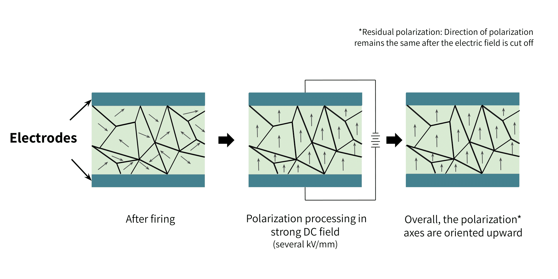
图3.合成压电材料的极化工艺
The most important thing to consider during poling is the geometry of the crystal, especially when applying the electric field; this greatly affects the sensitivity of the material.
极化过程中要考虑的最重要的事情是晶体的几何形状,尤其是在施加电场时;这极大地影响了材料的灵敏度。
Natural piezoelectric materials like quartz simply need to be cut with fine precision tools to the application’s required dimensions. However, these natural single crystal materials have very bad crystal stability and a limited degree of freedom.
像石英这样的天然压电材料只需要用精密工具切割成应用所需的尺寸。然而,这些天然单晶材料的晶体稳定性非常差,自由度有限。
On the other hand, fabricated piezoelectric materials are more stable and can be created with properties tailored to specific applications. Moreover, the support substrate required by fabricated materials doubles as the outer electrode of the piezoelectric sensor. The substrate material’s orientation is such that the direction of the deforming stress is perpendicular to the polarity of the generated charges. Figure 4 below illustrates this point.
另一方面,制造的压电材料更稳定,并且可以创建具有针对特定应用量身定制的特性。此外,制造材料所需的支撑基板兼作压电传感器的外电极。基板材料的方向使得变形应力的方向垂直于产生的电荷的极性。下面的图 4 说明了这一点。
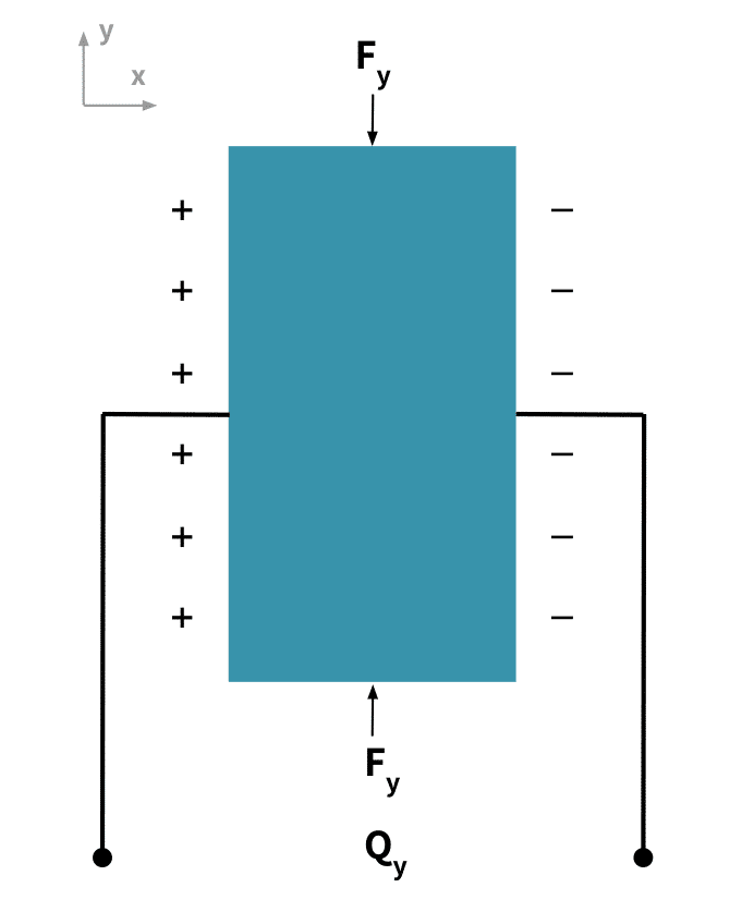
图4.应力方向和运动电荷方向
Sensor Characteristics 传感器特性
Both the piezoelectric sensor and the strain gauge have characteristics that make them ideal depending on the application. This section compares these criteria.
压电传感器和应变片都具有理想的特性,具体取决于应用。本节将比较这些标准。
Geometric Shapes and Designs
几何形状和设计
Strain gauges most often appear in strain gauge load cells. These are durable metal structures that house a strain gauge. The position of the gauge in the structure allows it to capture strains at that location; engineers exploit this fact by creating these load cells in different geometric shapes with different load point characteristics. This diversity allows the load cells to adapt to the needs of different applications.
应变片最常出现在应变片称重传感器中。这些是耐用的金属结构,装有应变片。仪表在结构中的位置使其能够捕获该位置的应变;工程师利用这一事实,将这些称重传感器创建为具有不同负载点特性的不同几何形状的称重传感器。这种多样性使称重传感器能够适应不同应用的需求。
By convention, the geometric shape of the gauge’s structural housing unit gives the load cell it’s name. Some examples of so-named load cells are beam, S-shape, disc canister, or planar beam. Piezoelectric sensors also include housing designs in these shapes. Again, the geometry of the sensor depends on the application requirements.
按照惯例,仪表结构外壳单元的几何形状为称重传感器命名。所谓的称重传感器的一些例子是梁式、S 形、圆盘罐或平面梁。压电传感器还包括这些形状的外壳设计。同样,传感器的几何形状取决于应用要求。
Generally, piezoelectric sensor designs are more compact and are more rugged in construction than those of strain gauges. Their small size and excellent dynamic response makes them suitable for highly sensitive applications. They have wide uses from medical robotics to acoustics applications.
一般来说,压电传感器的设计比应变片更紧凑,结构更坚固。它们体积小,动态响应出色,适用于高度灵敏的应用。它们具有从医疗机器人到声学应用的广泛用途。
Both types of sensors can be used for multi-axial applications, and can support compression, shear, or bending stresses.
这两种类型的传感器都可用于多轴应用,并可支持压缩、剪切或弯曲应力。
Other Specifications 其他规格
Original equipment manufacturers provide datasheets with the electrical specifications of their transducers. This section explains some of these characteristics appearing on the datasheet. The values of these and other characteristics help designers choose the appropriate sensor for the application; likewise, they give the performance metrics technicians use to calibrate the resulting measurement system.
原始设备制造商提供包含其传感器电气规格的数据表。本节将对数据表中出现的一些特性进行说明。这些特性和其他特性的值有助于设计人员为应用选择合适的传感器;同样,它们也提供了技术人员用来校准最终测量系统的性能指标。
The Force Range: 力范围:
This is the rated capacity (minimum to maximum accurately detectable force) in Newtons. The force range of the piezoelectric sensor is typically 5KN to 1MN. By contrast, the strain gauge sensor typically has a range of 5N to 40MN.
这是以牛顿为单位的额定容量(最小到最大精确可检测力)。压电传感器的力范围通常为5KN至1MN。相比之下,应变片传感器的范围通常为 5N 至 40MN。
Loading Conditions: 装载条件:
Piezoelectric load cells can only support dynamic loads such as vibrations, accelerations, and dynamic pressure measurements; strain gauge load cells can support both static and dynamic loads.
压电称重传感器只能支持动态负载,如振动、加速度和动态压力测量;应变片称重传感器可以支持静态和动态载荷。
Creep: 爬:
Strain gauge sensors have insignificant output drift when under a load for a long period of time; piezoelectric sensors have very large drift in output value, resulting in measurement errors for prolonged loading.
应变片传感器在长时间处于负载状态时输出漂移不明显;压电传感器的输出值漂移非常大,导致长时间负载时的测量误差。
Stiffness: 刚度:
Piezoelectric sensors have very high stiffness value. Strain gauges are more elastic and their durability depends on the load cell where they reside.
压电传感器具有非常高的刚度值。应变片更具弹性,其耐用性取决于它们所在的称重传感器。
Resonant Frequency: 谐振频率:
Unlike strain gauge transducers, piezoelectric sensors have a higher resonant frequency due to their stiffness. This value can be as high as 100,000Hz.
与应变片传感器不同,压电传感器由于其刚度而具有更高的谐振频率。此值可高达 100,000Hz。
Sealing: 密封:
Both sensor types are designed to have very excellent seals, offering a high degree of protection and operational safety in harsh environments. The most common sealing technique is the hermetic seal.
两种传感器类型都设计为具有非常出色的密封性,可在恶劣环境中提供高度保护和操作安全性。最常见的密封技术是气密密封。
Temperature Effects: 温度影响:
Both strain gauges and piezoelectric sensors are very sensitive to temperature changes. For both sensors, this affects their zero-balance, sensitivity, and linearity. Because of this, manufacturers use various compensation techniques: strain gauge sensors use self-temperature compensating gauges; piezoelectric sensors adjust for temperature effects with a charge amplifier.
应变片和压电传感器对温度变化都非常敏感。对于这两个传感器,这会影响它们的零平衡、灵敏度和线性度。正因为如此,制造商使用各种补偿技术:应变片传感器使用自温度补偿片;压电传感器通过电荷放大器调节温度效应。
Repeatability: 重复性:
Both sensors can be designed to achieve excellent repeatability, or agreement between the results of successive measurements.
两种传感器都可以设计成实现出色的可重复性,或连续测量结果之间的一致性。
Linearity: 线性:
Strain gauge sensors have a lower linearity error in comparison to piezoelectric sensors.
与压电传感器相比,应变片传感器具有更低的线性误差。
Sensitivity: 敏感性:
This is the rate of change of the output as the desired input varies. The sensitivity of the piezoelectric sensor depends on the material used and its geometry; it is rated in Pico Coulombs per Newton (pC/N). A strain gauge transducer’s sensitivity depends on the excitation voltage and the rated capacity value; it is rated in millivolts per volts (mV/V).
这是输出随着所需输入的变化而变化的速率。 压电传感器的灵敏度取决于所使用的材料及其几何形状;它的额定值为皮库仑/牛顿 (pC/N)。应变片传感器的灵敏度取决于激励电压和额定容量值;它的额定值为毫伏/伏特 (mV/V)。
Conclusion 结论
Both strain gauge and piezoelectric force transducers are of undeniable importance to many force measurement applications. The choice between them depends on the application’s requirements. Manufacturers’ data sheets give the transducer’s input and output characteristics used in making the design choice.
应变片和压电力传感器对许多力测量应用都具有不可否认的重要性。它们之间的选择取决于应用程序的要求。制造商的数据手册提供了用于做出设计选择的传感器的输入和输出特性。
Piezoelectric sensors offer excellent dynamic measurements, especially where compact size is a requirement. Strain gauge transducers are more common in heavy duty industrial applications, offering excellent dynamic and static load measurements. See Choosing the Right Load Cell for Your Job to learn which strain gauge load cell geometries are best suited for a particular application,
压电传感器提供出色的动态测量,特别是在需要紧凑尺寸的情况下。应变片传感器在重型工业应用中更为常见,可提供出色的动态和静态负载测量。请参阅为您的工作选择合适的称重传感器,了解哪些应变片称重传感器的几何形状最适合特定应用。
Other Resources: 其他资源:
- Force Measurement Glossary by Tacuna Systems.
Tacuna Systems 的力测量词汇表。 - Force and Weight Measurement Resources
力和重量测量资源 - An Overview of Load Cells by Tacuna Systems
Tacuna Systems 称重传感器概述 - The Versatile Strain Gauge Load Cell
多功能应变片称重传感器 - Connecting a Force Sensor to a DAQ
将力传感器连接到DAQ - All About Electrical Connections Of Force Transducers
关于力传感器的电气连接 - How to Read a Load Cell Datasheet
如何阅读称重传感器数据表
References 引用
- Piezoelectric Sensor, A Method for manufacturing a piezoelectric sensor and a medical implantable lead comprising such a sensor, US 8,626,313 B2
压电传感器,一种制造压电传感器和包含此类传感器的医疗植入式引线的方法,US 8,626,313 B2 - Comparative look at strain gauge and piezoelectric sensors by JAC Chapman, Elexsys
应变片和压电传感器的比较研究,作者:JAC Chapman,Elexsys - The Instrumentation Reference Book, Edited by Walt Boyes.
仪器参考书,由沃尔特·博耶斯(Walt Boyes)编辑。 - Jayant Sirohi, Inderjit Chopra , “Fundamental Understanding of Piezoelectric Strain Sensors,” Journal of Intelligent Material Systems and Structures.
Jayant Sirohi,Inderjit Chopra,“压电应变传感器的基本理解”,《智能材料系统与结构杂志》。